Table of Contents
- 1. Introduction & Overview
- 2. Technical Analysis
- 3. Technical Details & Mathematical Formulation
- 4. Experimental Results & Performance
- 5. Analytical Framework & Case Study
- 6. Critical Analysis: Core Insight, Logical Flow, Strengths & Flaws
- 7. Future Applications & Development Directions
- 8. References
1. Introduction & Overview
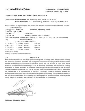
US Patent 6,612,705 B1, "Mini-Optics Solar Energy Concentrator," presents a novel approach to solar energy collection by introducing a lightweight, flexible, and cost-effective optical concentrating system. Invented by Mark Davidson and Mario Rabinowitz, the patent addresses a critical bottleneck in solar power: the high cost of photovoltaic (PV) cells. The core proposition is to use a large area of inexpensive mini-optical elements to concentrate sunlight onto a small area of high-efficiency, expensive solar cells, thereby dramatically reducing the overall system cost per watt.
The invention's significance lies in its departure from bulky, rigid concentrators. It proposes a system that can be "rolled up, transported, and attached to existing man-made, or natural structures," eliminating the need for expensive and complex support superstructures. This aligns with the broader industry trend, noted by institutions like the National Renewable Energy Laboratory (NREL), towards reducing balance-of-system (BOS) costs, which often dominate total installed costs.
2. Technical Analysis
2.1 Core Invention & Principle
The patent describes a system comprising a multitude of small, reflective elements ("mini-optics"), likely spherical or ball-like, embedded in a flexible medium. These elements are individually controllable, presumably via electric or magnetic fields, to orient their reflective surfaces to track the sun and focus its rays onto a fixed PV cell target. This creates a distributed, adaptive focusing array.
2.2 System Components & Architecture
- Mini-Optic Elements: Small balls or elements with a planar, highly reflective (e.g., metallic) surface.
- Flexible Substrate/Matrix: A sheet or film in which the mini-optics are embedded, allowing the entire assembly to be flexible.
- Actuation & Control System: A mechanism (implied to be electromagnetic) to individually or collectively orient the reflective surfaces for sun-tracking and focusing.
- Receiver/Target: A small, high-grade photovoltaic cell positioned at the common focal point of the oriented mini-optics.
2.3 Key Differentiators from Prior Art
The patent explicitly distinguishes itself from prior "twisting balls" or Gyricon display technology (e.g., used in early e-paper). While prior art used fields to orient balls for display purposes (e.g., black/white contrast), this invention repurposes the concept for optical concentration and energy conversion. It claims novelty in applying oriented reflective elements specifically for focusing light to increase energy density on a solar converter, a function absent in display-centric patents.
3. Technical Details & Mathematical Formulation
The fundamental optical principle is reflection and concentration. The geometric concentration ratio $C$ is a key metric, defined as the ratio of the collector aperture area to the receiver area: $C = A_{collector} / A_{receiver}$. For an ideal system with perfect optics and tracking, the solar flux incident on the receiver is multiplied by $C$.
The theoretical limit for a 2D concentrator (like a trough) is given by the sine law: $C_{max,2D} \leq 1/\sin(\theta_s)$, where $\theta_s$ is the half-angle of the sun (~0.27°). For a 3D system (point focus), the limit is: $C_{max,3D} \leq 1/\sin^2(\theta_s) \approx 45,000$. The patent's mini-optics system, by using many small elements, aims to approach these limits with a lightweight, adaptive platform. The effective focal length $f$ and the angular orientation $\theta_i$ of each mini-mirror are critical control variables to maintain focus on the moving sun: $\theta_i = \frac{1}{2} \arctan\left(\frac{d_i}{f}\right) + \frac{\alpha_{sun}}{2}$, where $d_i$ is the element's distance from the optical axis and $\alpha_{sun}$ is the sun's angular position.
4. Experimental Results & Performance
While the patent text provided does not include specific experimental data tables, it makes several performance claims based on the proposed design's inherent advantages:
- Cost Reduction: Primary claim is significant reduction in concentrator material and structural costs due to miniaturization and use of existing support structures.
- Weight & Flexibility: The system is described as "light-weight and flexible," enabling deployment on non-specialized surfaces (roofs, walls, vehicles).
- Robustness: By attaching to existing, sturdy structures, the system inherits their ability to withstand environmental stresses (wind, seismic activity).
- Implied Efficiency: The use of many small, individually controlled reflectors suggests potential for high optical efficiency and good tolerance to tracking errors compared to single, large mirrors.
Chart Description (Conceptual): A bar chart comparing "System Cost per Watt" would show the patented mini-optics system significantly lower than "Traditional PV (No Concentration)" and "Conventional Mirror Concentrator" systems, primarily due to drastic reductions in "PV Cell Area" and "Support Structure" cost components.
5. Analytical Framework & Case Study
Framework: Technology Readiness Level (TRL) & Cost-Benefit Analysis
Case Study: Rooftop Deployment vs. Conventional Solar Panel
- Scenario: A 10 kW residential solar system.
- Conventional Approach: 40 standard silicon PV panels (250W each), covering ~65 m² of roof, with racking system. High PV material cost.
- Mini-Optics Approach: A 40 m² flexible mini-optics sheet attached directly to the roof membrane, concentrating light onto a 1 m² array of high-efficiency multi-junction cells (e.g., with 40% efficiency).
- Analysis:
- Cost: Mini-optics reduces expensive semiconductor area by a factor of ~40 (the concentration ratio). The cost of the optics sheet and control system must be less than the cost of 39 m² of silicon cells for net savings.
- Installation: Adhesive-based attachment of a flexible sheet is potentially faster and simpler than mounting rigid panels with rails, reducing labor costs.
- Aesthetics/Integration: The low-profile, flexible nature offers better architectural integration.
- Risk: TRL is low (patent stage). Risks include durability of flexible materials, reliability of millions of micro-actuators, and optical efficiency over time (soiling, degradation).
6. Critical Analysis: Core Insight, Logical Flow, Strengths & Flaws
Core Insight: Davidson and Rabinowitz made a brilliant lateral move. They didn't try to improve the PV cell itself; they attacked the cost structure around it. Their insight was recognizing that the expensive part (the cell) needed to be small, and the cheap part (the light collector) could be made smart, distributed, and disposable. This mirrors the logic in other fields—think of how fiber optics use cheap glass to transport light to expensive transceivers.
Logical Flow: The patent's logic is sound: 1) High PV cost is the barrier. 2) Concentration reduces needed PV area. 3) Existing concentrators are bulky and need expensive support. 4) Therefore, create a concentrator that is lightweight (miniaturized optics) and uses existing structures (flexible, attachable). The leap to using micro-mirrors inspired by display tech is the inventive step.
Strengths:
- Elegant Cost Reduction Thesis: The core economic proposition is powerful and addresses a real market need.
- Modularity & Scalability: The concept scales from portable chargers to power plants.
- Decoupling: Decouples the durable structure (a building) from the potentially shorter-lived optical system, which could be more easily replaced.
Flaws & Gaps:
- Engineering Fantasy (Circa 2003): The patent vastly underestimates the monumental engineering challenge of reliably controlling millions of micro-mirrors outdoors for 25+ years. Actuator power consumption, failure rates, and control complexity are hand-waved. As the MIT Technology Review has often noted, moving from lab-scale micro-electromechanical systems (MEMS) to field-deployed macro-systems is a "valley of death."
- Optical Efficiency Skepticism: A flexible sheet with embedded balls will have gaps, non-active areas, and less-than-perfect reflectivity. The optical efficiency (land area to cell area) is likely lower than claimed, eroding the cost benefit. Studies on similar micro-tracking systems, like those reviewed by the International Energy Agency (IEA) PVPS Task 15, highlight optical losses as a major hurdle.
- Durability Black Box: No mention of encapsulation, UV degradation of the flexible substrate, cleaning of micro-scale features, or hail resistance. These are non-trivial for a product.
- Missed the Real Trend: Since 2003, the dominant trend hasn't been concentration, but the plummeting cost of standard silicon PV (Swanson's Law). The cost problem the patent aimed to solve was largely solved by scale and manufacturing innovation in plain old flat panels, making the added complexity of concentration less attractive for most applications.
Actionable Insights:
- For Researchers: Don't abandon the core idea. Instead of full sun-tracking micro-mirrors, explore static or passively adaptive mini-optics (e.g., light-guiding structures, luminescent solar concentrators) for building-integrated PV (BIPV). The value is in the form factor, not necessarily the tracking.
- For Investors: This patent is a classic "high-concept, high-risk" proposition. It would need a staged de-risking plan: first prove durable materials and static concentration, then add limited actuation. Bet on the team's ability to execute the materials science, not just the concept.
- For the Industry: The patent's ultimate legacy may not be a commercial product, but as a conceptual catalyst. It pushes us to think of solar collection as a distributed, intelligent surface—an idea now resurfacing in concepts like perovskite-silicon tandems on flexible substrates or solar skins.
7. Future Applications & Development Directions
The concepts in this patent, if developed with modern technology, could find niche applications:
- Ultra-Portable & Military Power: Roll-out sheets for remote operations, where weight and pack volume are critical.
- Vehicle-Integrated PV: Conforming to the curved surfaces of cars, trucks, or drones to provide auxiliary power.
- Agrivoltaics 2.0: Semi-transparent, flexible concentrator sheets over greenhouses, allowing diffused light for plants while concentrating direct light for energy generation.
- Space-Based Solar Power: Lightweight, deployable concentrators could be crucial for systems transmitting power from space, where weight is the primary cost driver.
- Future Direction - Hybrid Systems: The most promising path is to merge the form-factor advantage with newer cell technologies. Imagine a flexible sheet of mini-optics paired with a thin-film perovskite cell. The optics would boost the performance of the inherently lower-cost perovskite, creating a high-efficiency, lightweight, and potentially low-cost module.
8. References
- Davidson, M., & Rabinowitz, M. (2003). U.S. Patent No. 6,612,705 B1. Mini-Optics Solar Energy Concentrator. U.S. Patent and Trademark Office.
- National Renewable Energy Laboratory (NREL). (2023). Photovoltaic (PV) System Cost Benchmarks. Retrieved from https://www.nrel.gov
- International Energy Agency (IEA) PVPS Task 15. (2021). Enabling Framework for the Acceleration of BIPV. IEA Publications.
- Swanson, R. M. (2006). A vision for crystalline silicon photovoltaics. Progress in Photovoltaics: Research and Applications, 14(5), 443-453.
- MIT Technology Review. (2018). The Hard Truth About Advanced Solar Concepts. Retrieved from https://www.technologyreview.com
- Winston, R., Miñano, J. C., & Benítez, P. (2005). Nonimaging Optics. Academic Press. (For concentration limits and optics theory).